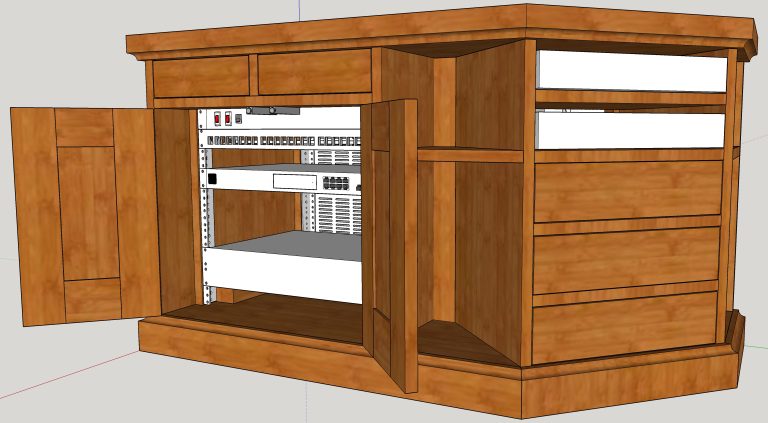
Recent additions to my homelab equipment and associated cables look unsightly sitting on top of a PVR cabinet I made years ago so I designed this new cabinet comprising a rackmount homelab unit with two doors and two drawers, and a unit with two open sections for PVRs and three drawers
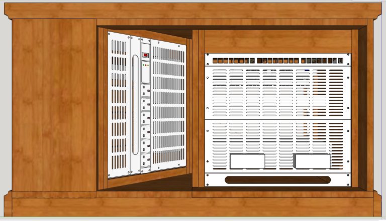
The devices to be installed within the cabinet are either black or silver but it was much easier to see the black construction lines on white surfaces during design
To simplify the design, not all devices have been included – e.g. thermostatically-controlled fans will be installed on the rear of the PVR unit to remove heat
Because this unit was designed to be only a little wider than the PVRs, I decided to mount the rear grilles and PSU in ‘portrait’ mode (world first?) instead of the usual ‘landscape’
To allow the units to be individually removed, I intended that dominos permanently glued into slots cut into the underside of the sides would dry fit (without glue) into corresponding slots cut into a single piece of oak covering the base
So the units were designed without individual bottom panels – which I later regretted and changed
Homelab/PVR Cabinet – Component Preparation – Rough Cutting to Size
Aside from thick oak boards for the top and a small amount of sycamore for drawer sides, these five oak boards will make the new cabinet
The boards were ripped …
… and cross-cut oversize making them easier to …
Homelab/PVR Cabinet – Component Preparation – Planing and Thicknessing
… plane and thickness square
These components were then cut slightly oversize from the squared boards
Homelab/PVR Cabinet – Homelab Unit
Six narrow pieces were dominoed and glued to create two wide sides
The twenty vertical slots are for more dominoes to join the sides to the back, the four horizontal slots will domino the sides together at the front using a narrow under-drawer horizontal brace and the eight small holes are for under-mount drawer runner euro screws
It was only after cutting the sides to length and assembling both units that I decided that they’d be much easier to remove if screwed to the base through individual bottom panels instead of being held in place with dominoes. The screws would be hidden by drawers or homelab equipment and three ‘drop-in’ triangular pieces would cover the remaining exposed surface of the base and – in conjunction with the plinth surround – the bottom panels’ unattractive end-grain
I’d designed the homelab unit to be 10U [the height of rackmounted devices is measured in ‘U’ where each ‘U’ is an integer-multiple of 44.45mm (1.75″). Fitting bottom panels between the sides in the usual way would reduce the unit to 9U but fitting them underneath the sides would retain the desired 10U
The sides after permanently glueing and dominoing – to the back, to the narrow under-drawer horizontal brace and to the bottom
The under-mount drawer slides are only test-fitted (and additional metal components have yet to be attached)
Prior to making the drawers (luckily), I revisited the SketchUp design and thought that one looked better than two (and would increase the storage space) so the central divider was cut out. This left two half-dominos visible on the upper side of the horizontal divider and another two visible on the inside of the back – but only when the drawer is removed
The central door panels were fitted, without glue (to allow for seasonal expansion and contraction) in rebates cut into the rails and stiles before the rails and stiles were glued and dominoed
Although it’s barely visible, the central panels were book-matched – a single thick board bandsawn down the middle then opened like a book – one for each door
In anticipation of this new unit, most of my new homelab equipment is rack-mounted. The front rackmount strips (supplied cut-to-length and M6 tapped) were set back from the front of the cabinet to allow sufficient room for patch cables then screwed through packing pieces to the cabinet sides
The two grey buttons under the horizontal divider allow the doors to be push-opened eliminating the need for handles. The hinges provide soft-close
Under-mount slides allow the drawers to be fully extended
The two (now cut in half) dominos that held the divider intended to fit between two drawers can be seen on the upper section of the back
The visible tone difference between the upper and lower sections of the sides of this and the PVR unit in the next image resulted from planing the bottom panels flush with the pre-sanded sides. It wouldn’t have been a problem if I’d designed the units correctly in the first place but will easily be removed by re-sanding the sides
The PVR unit is visible in the background
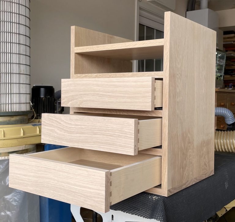
Homelab/PVR Cabinet – PVR Unit
This unit will house PVRs in the two upper open compartments
The three drawers below have sycamore sides to highlight the dovetails joints
The top two drawer fronts were cut from the same section of a wide board then ripped in two, providing a book-matched appearance
The soft-close, under-mount, push-to-open drawer runners eliminate the need for handles
The rear of the PVR unit showing the three pairs of undermount drawer runners (complete with the additional components that were missing from an earlier image of the network unit)
Homelab/PVR Cabinet – Base
The combined weight of the homelab devices is considerable so the base was strengthened with a core of scrap 38mm kitchen worktop
The pocket hole screws will hold four pieces of oak wrapping the base – the left-hand piece having already been temporarily fitted. The screws will be hidden under the units’ bottom panels and three triangular pieces referred to earlier
The base was increased to the desired height with oak pieces attached to the underside
Homelab/PVR Cabinet – Top
I wanted the top to be a minimum of 40mm thick, which requires rough-sawn boards of at least 50mm that I didn’t have in stock so we visited my ‘local’ (about 30 miles away) supplier
I love going to Whitmore’s Timber yard – they let me look around their huge stock of timbers from around the world and self-select the two boards of oak I wanted. They then moved the boards with a pallet truck onto a wooden box at a comfortable height so I could hand saw each in two to fit in the car
Only three of the four cut pieces were needed for the top, shown here before …
… and after planing and thicknessing square.
Oak is very expensive. The two board cost £216 so these three half-boards cost around £160 (just to make the top)
Homelab/PVR Cabinet – Assembly
I wanted cabling to be neat as possible so assembled the cabinet in the workshop at a convenient height while making the electrical connections
Two of the triangular spaces, one between the homelab and PVR units shown here – the other between the PVR unit and back – had triangular vertical pieces fitted at the rear to create 50mm wide flat backs that looked better than them going to a ‘point’
The ornament shelves are held in place with dry dominoes to allow the units to be removed separately
To allow easy access to the interior (for re-cabling etc.), the top is also removable, held in position only with an oak piece attached to the underside at the back
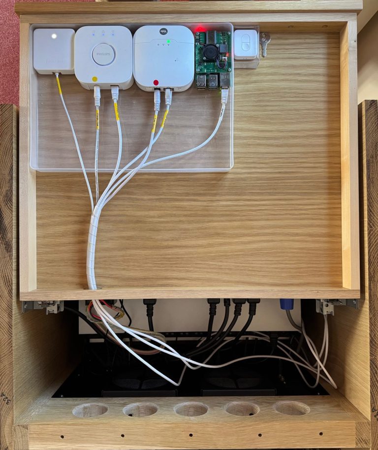
This and the following two images show the network unit from above with the front at the top
Network racks installed in companies have permanent infrastructure cabling fed through the backs into hard-wired patch-panels at the front but – again to make cabling as neat as possible – I employed patch panels at the front and rear of the network unit, linked by the ten custom-made-to-length cables shown here
This contravenes the generally good requirement of keeping connections to a minimum but I tested this during the design process without problem. It also allows devices to be connected at the rear that are hidden and easily disconnected when required
A single wall socket powers a 2U uninterruptible power supply (UPS – hidden underneath the silver device) that powers everything in the cabinet plus a few exterior devices including a wall-mounted CityFibre/Zen ONT (optical network terminal), a Synology DS723+ NAS (self-hosting this weblog) and a Synology DS716+ when temporarily connected during backups
The UPS then connects to this power distribution unit (PDU) via the blue Neutrik connector. The PDU then powers the PVR unit via the cable routed through the hole in the left hand side (as viewed) of the network cabinet, all devices in the network cabinet and a few outside
In-addition to eight 230Vac outlets, the PDU has three 5Vdc and three 12Vdc outlets (the green block), providing power to …
… (left to right) a SwitchBot Curtain Operator, Philips Hue Bridge (lighting), Yale Sync Smart Hub (alarm) and Raspberry Pi [employed as a NUT (network uptime tools) server]. The bulky, ugly (‘wall warts’) low-voltage supplies that originally powered these devices were cut off and scrapped
The PDU also provides 12Vdc to the wall-mounted CityFibre/Zen ONT (not shown)
The Yale Hub required 9Vdc necessitating wiring in a 12Vdc to 9Vdc converter between the PDU and Hub (the black block screwed to the drawer back just below the hole where the cable exits the drawer)
Five new holes were cut into the upper back to aid heat dissipation (not all images are in chronological order – which is how the holes have ‘disappeared’ from the next two images)
Still in the workshop, the two PVRs are plugged into a second PDU mounted on the rear of the cabinet (with additional devices to be plugged-in later). Power to the PDU is provided by the cable from the network PDU referred to earlier (just visible near the top of the image, between the two units)
After completing the wiring and test-fitting the devices in the workshop, the cabinet was dismantled and relocated to the living room
The black box on the rear of the PVR unit is a Samsung One Connect box providing the TV with signals via a thin fibreoptic cable that replaces potentially several thicker cables that makes it much easier and tidier to wall-mount a TV. The small white box is a 5-port network switch (now replaced by a 24-port rackmount switch shown in the next image)
The 3U two fan, low-noise heat extraction unit is fitted in the network unit
The finished homelab unit comprising (from top to bottom):