Our current kitchen looks dated so we’re going to replace:
The existing cabinets with Shaker style spray-painted units that I’ll make in the workshop
The floor tiles with Karndean Vinyl flooring
The gas hob with electric induction
The recycling fan with an extractor that will discharge air through the window wall (the workshop is on the other side of the fan wall) via ducting above the new wall units
The freestanding microwave and double oven (partly visible on the RHS of the next image) with a single conventional oven plus an oven/microwave combination, both to be housed in a tall cabinet on the opposite wall
The utility room (behind the door on the left) is always dark so we’ll remove the wall, door and radiator to create a lighter, open space
SketchUp 3D CAD software was used to design the new kitchen and create this and the following image that give an indication of the intended layout (colours are not necessarily representative – flooring and worktops especially – will be different to that shown)
A boiling water tap will be installed under the sink which – with the relocation of the ovens and new induction hob, extractor and 13A outlets for the centre island – necessitates significant rewiring
The view from the window
Kitchen Refurbishment – Materials
Plinths, doors, drawer fronts, cornices etc. will be made from the 19 sheets of Moisture Resistant MDF (MRMDF) on the left
Cabinet carcases etc will be made from the 29 sheets of American White Oak Veneered MDF on the right
These 48 boards weigh 1955kg, a significant portion of which will be hung on the walls 😱 (and the cabinets filled with bottles, heavy crockery etc, etc 😱😱😱)
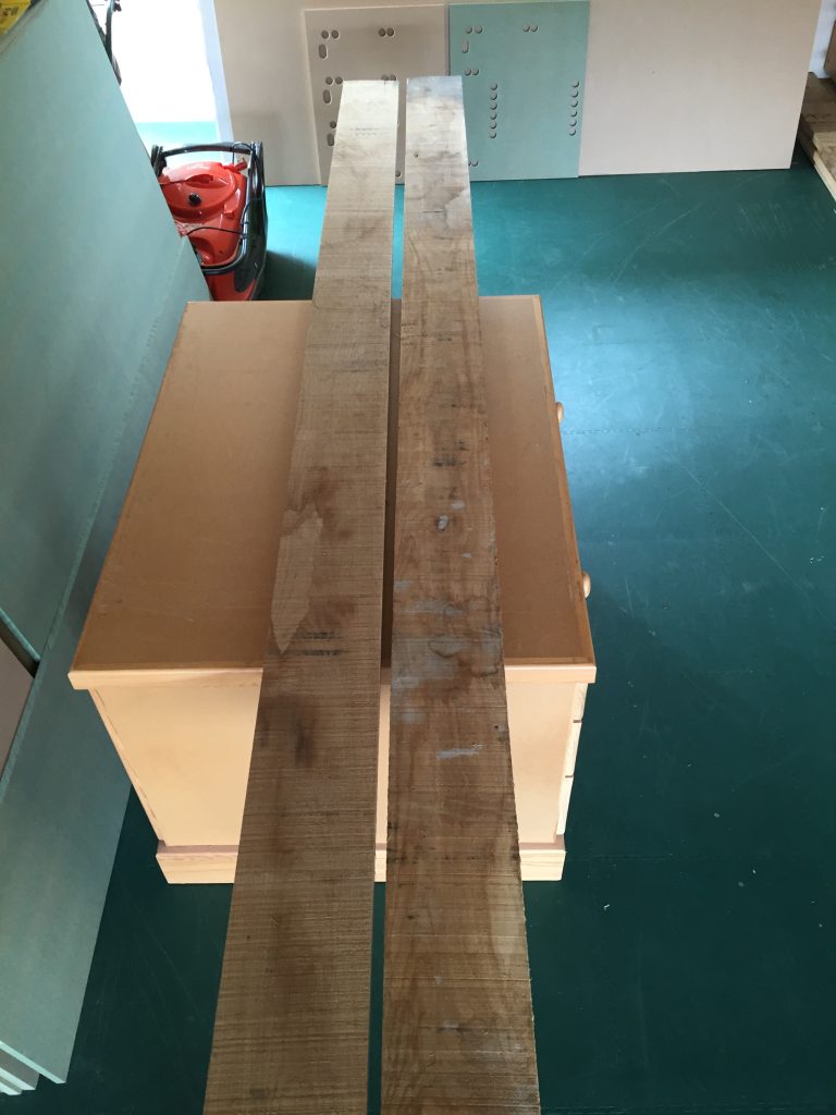
Faceframes and drawer boxes will be made from these 44 boards of oak (that a neighbour said looked like firewood but cost £1100)
As the faceframes will be painted it would have been less expensive to use Tulipwood (Poplar) but any excess would be waste whereas leftover oak could be used for other projects
Kitchen Refurbishment – Preparation
It’s easier to varnish the veneered MDF prior to cutting, so I rolled three coats of clear satin on both sides of all 29 sheets, a total of 174 sheet coats
I can only varnish three sheets per day so it’s going to take ten days (during which there’s no room to do anything else) and consume around eight 2.5 litre tins
Several holes need to be cut into the inside of every carcase so I made these two router jigs to ensure they’re precisely located
The 18mm MDF jig on the left will be used to route (“rowt”) the holes in four-drawer carcases. Circular holes are for drawer slide mounting screws, elongated holes are for below-drawer rail tenon mortises
The other 18mm MRMDF jig will be used to cut the holes in one-drawer-one-door carcases. In addition to the mortise and four slide screw holes at the top, the four LHS holes are for door hinge mounting plate screws, the twelve RHS holes are for shelf mounting pins (providing six shelf height positions per carcase)
If you’re wondering why the holes in the jigs are so large, it’s because the router is fitted with a 30mm guide bush that fits snuggly into the jig holes (the chamfered edges make location easy). A 5mm cutter then cuts the holes for the drawer slide screws, door hinge mounting plate screws and shelf pins while a 12mm cutter is used to route (“rowt”) the 35mm x 12mm rail mortises
Kitchen Refurbishment – Carcases
These are both sides of a four-drawer carcase after cutting the drawer slide mounting holes and under-drawer rail mortises with the router and jig
This cabinet has only three under-drawer rails but allowing for the setup of the Leigh jig used to cut the rail tenons, it’s much more efficient to make all 32 at the same time …
… from one and a half of these two oak boards
Bearing no resemblance to the boards from which they were made, these are the finished under-drawer rails
The countersunk holes are for screws that will eventually join the faceframe to the carcases
The first completed base carcase (the one at the bottom right of the earlier, second SketchUp image). At this stage the front edges are bare MDF but will be hidden by a faceframe
It stands on its plinth that I made earlier – the other sections’ plinths are partly visible standing vertically behind it. The 30mm green MRMDF from which the plinths are made will eventually be covered by painted kickboards
With the exception of the extractor fan carcase, the remainder were all made in a similar way, though the wall cabinets – having no under-drawer rails – were a little easier, and the tall oven cabinet – with many – a little more difficult
The extractor carcase obviously requires an open bottom, plus …
… a round hole in its top for ducting and a square hole in its back to access the electrical wall socket
The oval shaped pieces of wood – called ‘biscuits’ – are glued into corresponding oval slots to join the carcase components together. Biscuits were later superceded by dominos (more later)
The assembled carcase complete with test installation of the extractor fan complete with a short vertical section of round ducting and a round to rectangular 90º elbow
Kitchen Refurbishment – Faceframes
These are the faceframe components for the base carcase shown earlier (excluding beading that will be made and applied later). Perimeter joints are standard mortise/tenon but using these for the two cruciform joints would require very short (9mm), weak tenons on the vertical stiles. Instead, the bottoms of the two short upper stiles, tops of the two long lower stiles and the horizontal rail are all mortised. Handmade 80mm loose tenons (visible loosely inserted into the tops of the two long lower stiles) then join the upper and lower stiles through the rail
The faceframes will be painted (and are removable to make this task easier) so don’t need to match the oak carcase interiors. I used sycamore left over from a previous project for this one
The assembled faceframe complete with beading
Making the first faceframe took forever so I purchased a Festool Domino Jointer to replace mortise/tenons with mortise/mortise joints that are extremely easy to cut with the jointer. Mortise pairs are then joined with loose tenons called dominos
Making and attaching separate beads was also very time-consuming so I made a jig to cut the (just visible) butted-mitre joints using a router and mitre cutter
This faceframe has been dry (no glue) joined with dominos to ensure everything fits before being disassembled to route (“rowt”) the beads. To help prevent errors, the edges to be beaded were marked with black lines (but to maintain my impressive error-count, I added the unwanted line on the LHS of the left vertical stile)
Kitchen Refurbishment – Drawers
These 13 boards are for the drawers …
… cut, planed square and thicknessed slightly oversize …
… then dovetailed using another Leigh jig and rebated for the drawer bottoms …
… and assembled
The rectangular cutouts in the drawer backs accomodate …
… Blum soft-close under-drawer runners. The drawers can be easily inserted and removed without tools, leaving only these release/adjustment clips
The underside of the front should look similar to the back (at the top) except for much-wider runner cutouts but I was concerned that too little material would remain to prevent the bottom of a heavily-loaded drawer sagging and breaking the centre piece. I decided instead to remove the centre piece completely and extend the drawer bottom past the drawer front by 12mm. A rebate cut into the false front would then support the bottom along its entire length when the false front was attached to the drawer box
Aside from this test fitting, the runners would (of-course) remain in the carcase when drawers are removed
Kitchen Refurbishment – Doors
Doors and drawer fronts will be painted so were …
… made from MRMDF that doesn’t suffer from the seasonal movement of oak …
Kitchen Refurbishment – Wine Cabinet
Throughout the design process I’d been concerned about the huge weight of the wall cabinets. The cabinet above the hob could have additional fixings through both sides – adjacent the window wall and adjacent the tall oven cabinet – but the cabinet opposite could only have additional fixings into the wall. Alison came up with the bright idea of making a wine cabinet that would fit underneath the otherwise-unsupported LHS
The wine cabinet is primarily made from MRMDF but I was concerned that its relatively soft edges would be damaged by bottles so (hard) oak strips were applied to the leading edges of all components prior to assembly …
… like this (the different materials will be invisible when the cabinet is painted)
The top is set back to allow for the underside of the faceframe on the wall cabinet above (when fitted)
Kitchen Refurbishment – Cornices
Cornices were also primarily made from MRMDF
This is the base of the cornice for the tall oven unit. The slots are for star knobs that will be used to hold the cornices in place while allowing easy removal for cleaning of them and the top of the units
Cornice faces are at 45º to the base making them impossible to clamp while glue dries
Instead a compressor coupled to a pneumatic pinner was used to fire very thin pins through the base into the faces to hold them in position while pocket-hole screws pulled the joints together
The pocket-holes were then plugged, before …
… the oak top-cap was glued – again held in place during gluing with pins. The pins are extremely thin and headless leaving only tiny holes to be filled prior to painting
To maintain my error count, I made the short leg of the primed cornice directly above, too short
Kitchen Refurbishment – Painting
I tried painting using the ‘roll and tip’ technique, often used for boats. It worked well for large flat items such as doors, drawer fronts and even cornices but attempts to achieve a good finish on the faceframes failed
The intricate bead profile made hand applying three or four coats of excellent Tikkurila Otex Akvaprimer and sanding between each one, a very time-consuming laborious task. After what felt like (and often was) days, my lack of skill would then spoil the perfectly prepared surface
I couldn’t do anything to reduce the sanding time but after a suggestion from a good friend (thanks Charles) invested in an Graco airless sprayer. The painting time of all components was hugely reduced – for faceframes, from more than an hour per side per coat to under one minute. More importantly, the result after very little practice, was always perfect
Kitchen Refurbishment – Old Kitchen Removal
With most of the cabinets made, everything (including the drylining) was removed from the kitchen to allow the electrician to do his work. Removing floor tiles was much easier than expected, requiring little more than a light tap with a hammer to a bolster placed under the tiles’ edges. Removal of residual adhesive was much, much more difficult – thanks to a good friend and next door neighbour Jude for his help with this tedious task
I’d previously installed the backboxes exactly where I wanted them and cut the conduit channel for the centre island wiring. When the sparky had finished the channel was filled with a small amount of concrete and the cable tied to the light fitting to keep it off the floor while …
Kitchen Refurbishment – Flooring
… flooding the floor with self-levelling compound (thanks again to Charles for his help)
Kitchen Refurbishment – Walls
Still having nightmares about the weight of the wall cabinets, I decided to line the walls with 30mm of plywood (18mm with cable channels then 12mm on top, that I bevel-edged with a hand plane) that I thought would be stronger than 12mm plasterboard and 18mm air gap (except where there are dots of adhesive)
An unexpected, time-consuming part of this job was fitting the two relatively small pieces above the window, one on the wall and the one below it within the reveal that required the lintel to be drilled and tapped to receive the fixing screws
All the joints were taped, then they and the screwholes were filled before the walls received a thin skim coat of plaster, that was then lightly sanded and …
… painted
Kitchen Refurbishment – Interior Plumbing
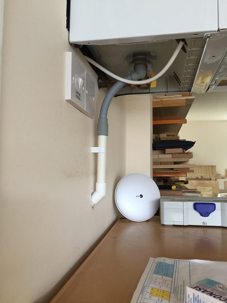
During refurbishment of the kitchen, boiler condensate drained into a container placed on top of a vegetable cabinet in the workshop
Before installing the new cabinets, new pipework was routed through a hole drilled at 45º through the workshop wall …
… into the kitchen and along the walls towards the sink …
… and connected to the new interior drainage pipework
To keep the plumbing as neat as possible within the under-sink cabinet (the only one that has no back), I assembled the manifold from push-fit fittings, mounted it on a piece of oak and screwed it to the wall. Counting from the top, cold water enters at row 2 via the oval cutout and is distributed to: Row 1: A filter that feeds the boiling water tank and tap (filtered) Row 2: The tap (unfiltered) Row 4: The dishwasher and garden tap
Hot water enters at row 3 via the oval cutout and feeds the hot (not boiling) water tap. All five hot/cold outlets are fitted with valves
The position of the outlets for the exterior trap (just visible on the right hand leg) and garden tap were different to the original, so …
Kitchen Refurbishment – Exterior Plumbing
… a new outlet hole was drilled, the old one filled and the garden tap and trap …
… relocated to the left (the old red tap wall plugs were later removed and the area surrounding the trap concreted)
Kitchen Refurbishment – Installing the New Kitchen
The base cabinet plinths and cabinets were installed and the Karndean vinyl flooring laid (thanks yet again to Charles for his help)
The wires dangling from the wall top left and top right (just visible) will eventually power under-cabinet lighting
The board behind the hob on the right protects the walls until they’re tiled while the box in the middle of the floor protects the island cable
The old oven still in its original unit was wired into one of the new oven outlets until the new tall oven unit could be installed …
… like this
With help (thanks again Jude), the first wall carcase was carried into the kitchen and lifted onto wooden blocks placed on the worktop. They provided just enough clearance when lowered to slide these two motorcycle jacks (rated at 500kg and purchased exclusively for the task) into position, though further apart than in this image. The jacks were then raised until the wine cabinet could be inserted to support the LHS. The RHS jack was adjusted until the carcase was level and sixteen holes drilled through pre-drilled, countersunk holes in the carcase, through the plywood and into the walls. Friulsider 10mm x 140mm frame fixings fastened the carcase to the wall
For the opposite wall, the extractor fan complete with short section of round ducting and the round to rectangular 90º elbow were installed into the carcase
The carcase was only a few mm narrower than the gap betwen the wall and oven unit and would be difficult to manoeuver into position. To make it as easy as possible, a large piece of excess worktop was placed on top of a free-standing workshop table to make the scrap and real worktops the same height. A large piece of MRMDF was then placed on top of the scrap worktop and the carcase lifted onto it. Both the MRMDF and carcase were then slid into the gap
Jude and I lifted the carcase just enough to allow Alison to slide the jacks underneath that were used to raise and hold the carcase in position while securing it to the wall
An overlength piece of rectangular ducting was then fed from outside through a hole I’d previously cut into the window wall into the rectangular to round 90º elbow, marked for length, removed, cut and replaced permanently