Day one after removing the washbasin, toilet, wall tiles, shower cubicle wall, shower tray, power shower and plasterboard from the walls
Then the floor was removed …
… and part of the lower section of the old stud partition wall to improve access to the soil and waste pipes
The old shower drain pipe (the stub of which which can be seen temporarily sealed with a plastic bag) was routed under the old shower tray but it’s above the new shower former and can’t be used
Here, the former is used to determine the routing of the new pipe
Three joists had to be drilled to accommodate the new shower pipe – a section of which is visible going through one of the joists
The old pipe drained directly into the vertical soil pipe but the only option for the new one is to replace the old horizontal section from the toilet with two new pieces and a boss (shown immediately to the right of the new shower pipe)
Like this (apologies for the blurred image)
The boss (now grey – the only readily available replacement after making a mistake fitting the white one) has been solvent welded between two new pieces of soil pipe and the shower drain pipe welded to the boss
The remainder of the shower drain under the former was then temporarily screwed together and tested by running a garden hose from the workshop through the en-suite window into the shower trap
A new washbasin waste pipe connected first to the bathroom which backs onto the en-suite, before …
… continuing to the location of the new washbasin
The new soil pipe fittings are also shown including the black pipe in the lower left corner that was supplied with the metal frame for the wall-hung toilet …
… shown here with the toilet pan temporarily connected to check for leaks …
… and here with the pan removed
The old centrally located radiator is to be replaced by two radiators placed under each window so pipework has to be added and re-routed
To ensure that the distance between each pair of wall pipes was exactly the same as that between the radiator valves, a temporary U-shaped section was assembled with the short pieces inserted in the valves while the 90º joints were soldered to the longer piece. The U-piece was then attached to the wall piping using the valves shown in the image while the wall pipes’ 90º bends were soldered
This is the left-hand radiator pipework – the process being repeated for the right-hand side. By closing the valves or leaving the U-shaped piece attached with the valves open, the heating could be refilled and used if necessary
As underfloor heating will be installed, insulation panels were laid on battens screwed to the joists to help prevent heat dissipating into the void between the ground and first floor …
… then the floor was overboarded with plywood
The box on the left covers the sloped ceiling above the stairs
The underfloor heating temperature probe sits in a channel routed in the plywood flooring – the white tape keeping it in place until the floor is tiled
The new radiator pipework has been plastered into the walls
The cables for radiator heating elements are just visible
With the help of a good friend (thanks, Charles), the walls were dry lined with moisture-resistant board
… and the joints filled …
The oblong shaped section on the ceiling is where the old shower wall was located. The circular patch to the right is where one of the two original lights were fitted
Another view
The cable provides power for the mirror shaver socket, lights, demister pad and clock
Mounting screws and water feeds for the basin are below
Blue polystyrene wrapped over the basin waste pipe was intended to prevent me bumping into it (but didn’t)
The window wall was far from flat. I wasn’t sure I could correct this during tiling and so plastered it flat first. With the benefit of hindsight, it would have been quicker to remove the plasterboard from all four walls instead of just three and a bit
There wasn’t sufficient room to fit the travertine tiles in the window reveals without encroaching onto the window, so the plasterboard was removed, the gaps filled with foam and the tiles fitted directly to the brickwork
Wooden battens were fastened to the wall where the radiator wall fixings would be fitted in order to ensure a firm fastening
The walls and floor were primed and tanking tape applied to the corners, wall/floor intersections and floor joints …
… then tanking membrane applied to the floor …
… and liquid rubber tanking painted onto the walls
A level batten was then fitted around the walls to support the first course of tiles
And tiling commenced on the far wall
Tiling is fairly-well advanced while the ceiling undergoes repairs
If you’re wondering why I didn’t repair the ceiling before fitting the lights and tiling the walls …
… so am I
The repaired and repainted ceiling awaiting re-fitting of the lights
With the wall tiling completed and the mosaic tiles fitted in the shower area, the underfloor heating mat is laid
There weren’t many size options – the next size up was too large
The floor tiles were fitted and all wall and floor tiling spacers removed …
… then the tiles were grouted and cleaned
With the central heating drained, the valves were removed from the radiator stub pipes, the pipes cut to length, the radiator brackets fitted …
… followed by the radiators …
… complete with heating elements to dry towels during the summer when the central heating is off
The mirror was fitted, …
… the washbasin …
… and the toilet and flush plate
Another view of the mirror, washbasin and toilet
During one of the warmest Septembers on record, several miserable days were spent in the loft plumbing and wiring the loft-mounted digital shower mixer and heat-recovery ventilation
This takes low pressure hot and cold water feeds and pumps high pressure mixed water down the green pipe on the left
A digital shower sounds gimmicky but it greatly simplifies installation/cleaning and maintenance
The digital mixer is controlled wirelessly by this remote controller, the size of a fat mobile phone. The shower is switched on and off via the lower button while temperature and flow rate are adjusted using the other four. During use, the display indicates either time of day or temperature plus flow rate. It remembers the previous settings so all that’s normally needed is the on/off button
The unit can be mounted within the showering area away from direct spray or up to 10m away. Since the shower is controlled remotely it overcomes the problem of getting a cold wet arm when reaching into the shower to turn on a conventional manual mixer valve
With no conventional mixer to install there’s no need run pipes in the cavity wall or to tile around an exposed mixer unit.
The green plastic pipe shown in an earlier picture runs inside the chrome riser bar that comes down from the ceiling
The lower end of the riser bar showing the absence of a conventional manual mixer valve
The loft is also the location of the heat recovery unit (apologies for another blurred image but there was little room to take photos)
The unit removes warm, stale air via a ceiling vent above the shower area and discharges it via a new tile vent on the roof. Fresh air, drawn in through another new roof tile vent is warmed by a heat-exchanger within the unit and enters another ceiling vent at the other end of the en-suite
I have no head for heights (Alison says I get vertigo when I put my shoes on) but another good friend (thanks, Pete) offered to fit the new roof vents
This is one of two pipes connecting the heat recovery unit to the exterior via two new roof vents (again, apologies for the picture quality). They’ll be wrapped in insulation later
Because the heat recovery unit works with warm air, condensate has to be removed. The soil stack passes through the loft near to the heat recovery unit and was selected as the discharge route. As the stack required cutting to install a new boss and adaptor for the condensate discharge pipe, it was easier to completely remove the portion of the stack that went through the roof and cap it within the loft using an air-admittance valve
One of the two roof tiles that would otherwise have become redundant after fitting the two new roof vents was used to replace the old tile that had the hole through which the soil stack passed
The heat recovery unit’s condensate pipe discharges through the black and white adaptor fitted into a new boss that was solvent-welded to the soil stack
With the shower screen fitted, the en-suite refurbishment is finished
Another view …
… and another …
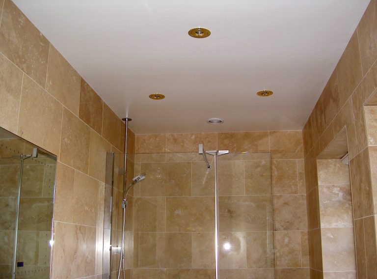
and the last one, showing the ceiling lights and the (white) extract vent for the heat recovery unit