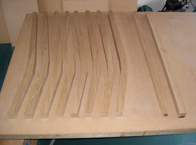
Six boards of rough sawn European Oak for a new dining room table and four chairs
The four boards on the left are for the table – the square-sectioned board for its legs, next is the board for the rails then two for the top
The two boards on the right are for the chairs
Dining Table – Component Preparation – Rough Cutting to Size
All components are initially cut oversize
Here, both table top boards have been cut in half and the leg board cut into four
Then the rail board is cut in three
Dining Table – Component Preparation – Planing and Thicknessing
Timber merchants apply paint in an attempt to equalise drying between the faster-drying ends and middle
Despite this, rough sawn boards still bend, bow, cup and twist as can be seen here in the legs, and …
… here in one of the three rail pieces
The next step is to square all components
Starting with the legs, the first operation is to create a flat surface by repeatedly passing the timber over the planer’s rapidly rotating blades while pressing down firmly down onto the table
The face of one leg (shown inverted) after one pass
All four legs now have one, flat face
Then, with the planer’s fence set at 90º to the table …
… the previously flattened faces are repeatedly passed over the blades while pressed firmly against the fence (not the table) to create a second flat face adjacent – and at 90º – to the first
In the previous image – taken prior to planing – the gap between the flattened face of the board and top of the fence was caused by the underside of the board not being at (in this case, less than) 90º to the flattened face
In this image it’s a little difficult to see that the top-right corner of each leg is 90º but obvious that they’re not square …
… until, after passing each leg repeatedly through the thicknesser – with each of the two flat faces down in turn – the legs are square and the final thickness
The rail board after planing and thicknessing to the required thickness then ripping and cross-cutting to create six blanks for the centre, side and end rails
During initial planing of the boards for the top, the irregular removal of material highlights cupping and twisting of rough sawn boards …
… that is removed by a few more passes through the thicknesser
Then board edges are planed square and the light-coloured sapwood removed
Dining Table – Component Preparation – Jointing
The legs are cut to final length and mortised for the rail tenons …
… then the two inside faces of each leg are tapered and a small chamfer applied to all edges except the top
The side and end rails with tenons cut for the leg mortises and the undersides chamfered (shown upside-down)
The side rails are too thin to be mortised for centre rail tenons so ‘biscuits’ (oval shaped pieces of wood) will be used instead
Returning to the table top components, more slots are cut for biscuits to increase the joint strength and prevent the board edges from ‘creeping’ during glueing
Dining Table – Assembly
After glueing the eight rail tenon to leg mortise joints and four centre rail to side rail biscuit joints
Close-up of a leg to rail joint
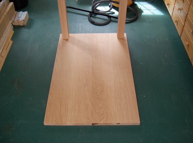
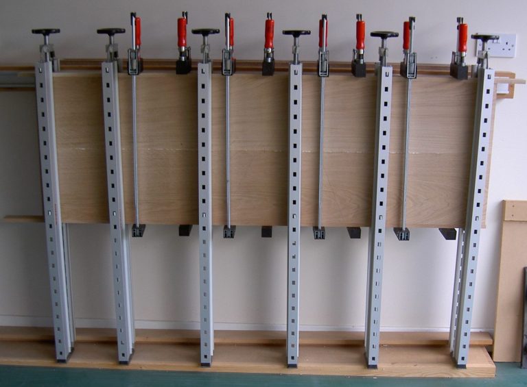
One half (two boards) of the table top clamped while the glue cures
The wall-mounted Plano clamps simultaneously apply pressure across the width and thickness – the latter helping to prevent the boards from cupping as the glue cures
Before glueing the two table top halves, the visible glue joints running down the centres will be removed by the sanding machine (the white machine partially visible in the top right corner three images earlier)
The entire table top is too wide to fit into the Plano clamps so it was clamped on top of a flat surface and checked with a straight edge. If it hadn’t been flat, additional clamps – perpendicular to those in the image – would have been used to correct the problem before the glue cured
The top is also too wide (and far too heavy) to be fed through the sanding machine (visible again on the right) so the joint is planed and the entire surface sanded again by hand
Dining Table – Finishing
The finished table after varnishing
Chairs – Component Preparation – Cutting Oversize
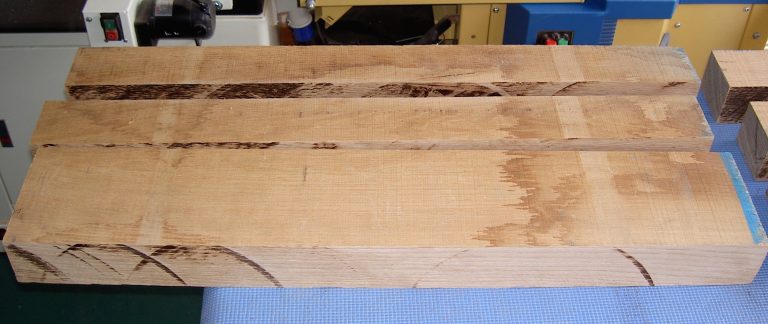
The two remaining boards to be used for the four chairs prior to …
… and after cross cutting
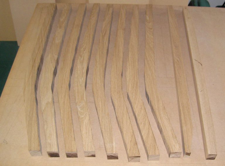
It doesn’t look like much material but these seven pieces are all the oak needed to make four chair frames (excluding seat pads and corner blocks)
An MDF template used to mark out the eight back legs prior to cutting on the bandsaw
At this stage, only the undersides of the boards have been planed (to create a flat reference face) because it’s almost impossible to see pencil lines on planed oak
… and after cutting on the bandsaw
The two offcuts are just large enough to create four of the eight stringers (that connect the front and back legs below the side rails)
The offcuts after planing one face/edge square and removing some excess material
The dining table was easy to make because all joints meet at 90° but chairs are much more difficult because several different – often compound angles (two on one joint) – are needed. To ensure that all the angles were correct I drew a full sized plan on a sheet of MDF and used it to create a full sized prototype from scrap Meranti. The prototype was dry assembled and sat on to ensure that it was comfortable prior to cutting the oak
The component in the lower left corner of the image is one of the two prototype meranti stringers
Returning to the back legs – all eight after thicknessing to 50mm
The bandsawn faces on the left and right of each leg are still rough but because they’re not flat, can’t go through the thicknesser so they were cleaned by hand using a small block plane …
… which took all morning
The full size chair plan is partially visible on the sheet of MDF beneath the legs
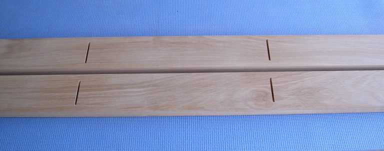
Putting the back legs to one side, these two pieces will yield all eight back slats and all eight back top and bottom rails
Each piece is ripped into three
In this and the next image, the four narrower pieces are for the eight back slats, …
… one of the two wider pieces is for the four top rails and the other for the four bottom rails
The four back slat pieces after cutting each into two on the bandsaw
The two wider pieces shown two and three images earlier were each cross cut into two
This one has been marked for two of the four top rails
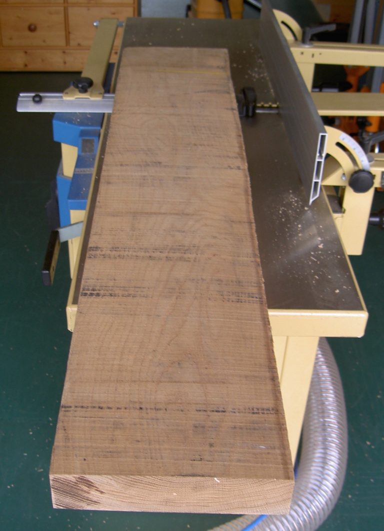
Another view of the same board showing the importance of planing one flat surface before doing anything else
Planing is performed by pushing the board (towards the window) by hand (😱) over the rapidly rotating blades on the upper (planer) table on which the board is sitting
To obtain the desired thickness, the board is placed planed face down on the lower (thicknesser) table (marked with a black spot) and pulled by powerful rollers under the blades (shared with the planer) through the machine away from the window
The remaining three boards will be used to create all eight front legs and side rails
After ripping on the table saw
The four unplaned pieces on the left will yield all eight front legs
The stack on the right comprises all eight stringers, all four back rails, all four front rails and all eight side rails. They’ve been machined to the desired thickness but still require cutting to length
Chairs – Component Preparation – Joints
Aside from the thickness of the top rails (the reason to be explained later), all components now have their final dimensions
Here are the blanks for one chair back comprising two legs, a top rail, back rail and two slats
The next step is to cut 72 mortises and 72 tenons
All four top rails (top of image) and back rails mortised and tenoned. These are the easy ones as none of the cuts are angled
A mistake just visible on the mortise in the top left of the image will be hidden by the back slat
A side view of the back slats after cutting top and bottom tenons
The chair backs are angled at 6° from the vertical but postponing the angle until 30mm above the back rail (just visible) allows the lower slat tenons to be cut at 0º
The back legs mortised for the top and back rails
With most of the joints for chair backs cut, they’re dry (no glue) assembled to ensure that everything fits as intended …
… like this
Eventually the top will be shaped to a peak
The top and back rail mortises in the legs were cut 1mm closer together than the corresponding measurement between the tenons to ensure tight joints between the back rail and slats …
… and slats and top rail
The top rails still require hand-planing flush with the back legs’ taper and mottling on the slats – caused by pressure from the blue mat when they were sanded – will be removed by prior to varnishing
The chair back sections disassembled and mortised for side rails and stringers
The front legs mortised for side and front rails
It’s difficult to clamp when mortising close to component ends so the legs were machined in pairs before cutting in two …
… like this
(stringer mortises can’t be cut until after the legs are tapered)
The 8 lower, inside faces of the back legs were tapered
As were the 16 inside faces of the front legs
Mortises are easy because they’re perpendicular to the faces into which they’re cut but the corresponding tenons are much more difficult
Because the seat fronts are 8° wider and 2° higher than the backs, the corresponding side rail and stringer tenons require compound angles (two on each) of 8° and 2°
The 8° angles in the side rails can be seen here …
… and the 2° angles here (two rails stacked for emphasis)
Because the back leg tenon inclines the side rail 2°, the front leg tenon declines at 2° in order to return the front leg to the vertical
Top rails are cut to a peak
After cutting stringer mortises, the chair sides are dry assembled …
… then disassembled and all components fine-sanded prior to assembly
Chairs – Frame Assembly
The back legs are glued as a sub-assemblies …
… as are the front legs
Then – on a flat surface – the back and front-leg sub-assemblies are glued to the side rails and stringers
Packing pieces prevent the clamps – capable of providing huge pressure – from ‘bruising’ the chairs. The stringer clamps’ back leg packing piece is angled to keep the clamp heads parallel which reduces the likelyhood of them creeping up the leg when tightened
All four chair frames after glueing
Chairs – Corner Blocks and Seat Pads
A small section of this board will be used to make the sixteen corner blocks …
… like this
Because the chair side rails incline at 2º, the corner blocks are more complex to make than their simple appearance suggests
The gap between the top side of blocks four and five in the upper row and the underside of the same blocks in the lower row is caused by the blocks having to be angled at 2º (in addition to the obvious angled cuts at both ends)
The 2° angle referred to in the previous image means that the blocks are parallelogram shaped when viewed from the front, creating this inverted V shape when placed together
The ‘pockets’ accommodate the screws that are used to fix the blocks to the chair rails
The gap between blocks four and five on the lower row is again visible
The corner blocks fitted to the frame – shown from above …
… and below
The blocks increase the chair’s rigidity and a secure means of attaching the seat pads …
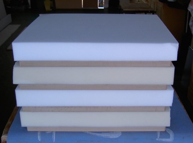
… like these (all four, stacked)
The pads will be upholstered and won’t be seen so they’re made from MDF which doesn’t suffer from seasonal movement, unlike oak
The recessed holes accomodate T nuts …
… like these (with their corresponding stainless steel M8 countersunk socket-head screws) …
… that are hammered into the recesses until they’re flush with the pads’ surfaces …
… and the pads test-fitted to ensure alignment of the screws and T nuts …
Chairs – Upholstery
Thick foam is glued to the seat pads with spray-mount adhesive …
… then trimmed to size and the upper edges chamfered (easily) on the table saw
Again, from above
Then wadding is placed over the foam and stapled to the pad
Fabric is wrapped over the pad, foam and wadding and stapled to the underside of the pad and the upholstered seat finally attached to the chairs